
Shades Solenoid Saver - Installation Guide
We provide this installation guide as information to help you install the Shades Solenoid Saver filter screen.
Contents
You should find the following parts in your Solenoid Saver kit (as shown here): 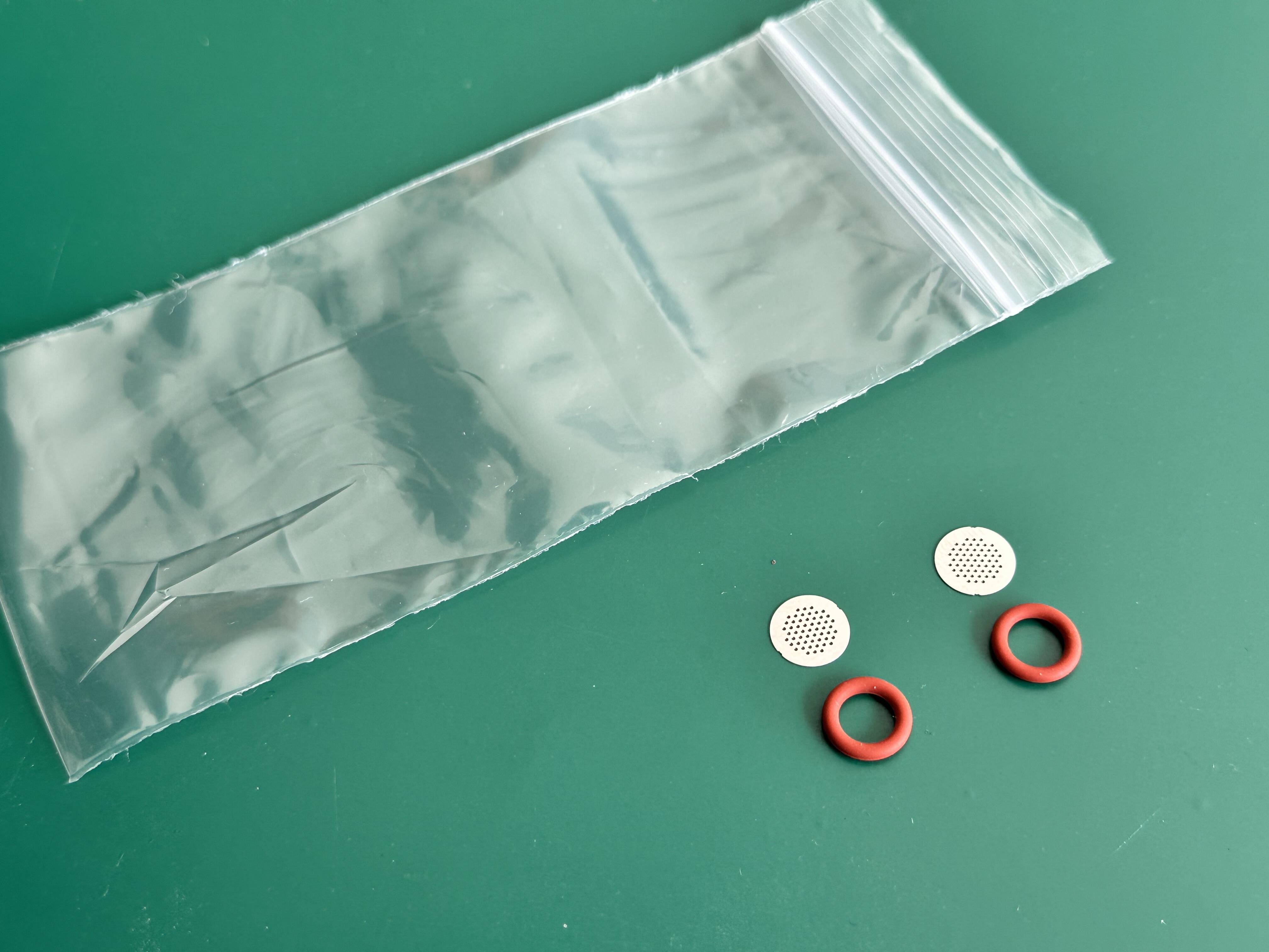
2 x red silicone o-rings
2 x Shades Solenoid Saver filter screens
We provide two o-rings and two screens to help with ongoing maintenance - though within any Classic installation you will only use ONE screen at any one time.
Introduction
Whilst installing the Solenoid Saver isn't difficult, in order to easily fit / install the solenoid saver filter it is recommended that you are familiar with the internal components of the Classic, and have knowledge of using basic tools, how to remove the top of the machine and what / where the various internal components are.
The following images and install notes relate to a Classic E24, and will be almost identical to installation on a Classic Pro (Classic 2019) or a Classic Evo (Classic 2023) - though installation on an original Classic should be similar but slightly easier (you can usually remove the solenoid valve without removing the pump on earlier models.)
Should you be using a Shades of Coffee brew pressure gauge with a solenoid valve brass gauge adaptor, then we'd recommend that you install the Solenoid Saver screen within the group adaptor (ie between the gauge adaptor and the group head).
If you know what you're doing inside a Classic, and don't need any real help - then just read the TLDR below... otherwise skip to the "More detailed instructions" below.
TLDR
For anyone familiar with the internal workings and components of the Classic - the TLDR is "Remove the solenoid valve and the two associated red silicone o-rings that are used to seal it to the group; fit ONE of the solenoid saver screen filters in the RIGHT port of the solenoid valve (ie the side closest to the steam knob) and then fit the original (if it's reusable, and they usually are) o-ring on top of the screen. Fit the other (left side) o-ring within the solenoid valve and carefully. Check photos further down this page to see how the valve should then appear. Then refit the solenoid valve - tightening it securely. Finally, test for any leaks by performing a water back-flush with a blind basket."
More detailed Instructions
Firstly, if you have limited knowledge and experience of the internal components of the Classic then we'd strongly recommend taking photos of your machine as you progress through the installation. This gives you a great record of where pipes/wires/connections originally went - and it's often invaluable to have images of your machine if you later run into issues when reassmebling.
So, initially remove the top of the machine to gain access to the internal components, by loosening the two screws at the top/rear of the filler funnel - lifting the rear of the filler funnel and sliding the front of the cup-warming tray from the mounting above the switches at the front.
You'll usually need to remove the green/yellow earth wire(s) from the cup warming tray if you want to remove the lid entirely - though you can often leave them connected and just place/support the lid at the side of the machine.
On an original Classic (not a Classic Pro / Classic Evo / Classic E24) you can probably skip this next step, which is to remove the pump in order to gain easier access to the solenoid valve.
On all other machines you will usually have to remove the pump from the machine in order to provide sufficient access to the solenoid valve mounting screws. If you've previously removed the solenoid valve from your machine and you're confident of doing so without removing the pump then you can obviously do so,
You can see the inside of the Classic in the image below. There is one pump mounting screw (Philips head) in-front of the pump, close to the side wall - and there is a second (hex head) screw behind the pump, close to the centre of the machine (you can see this screw on the image below).
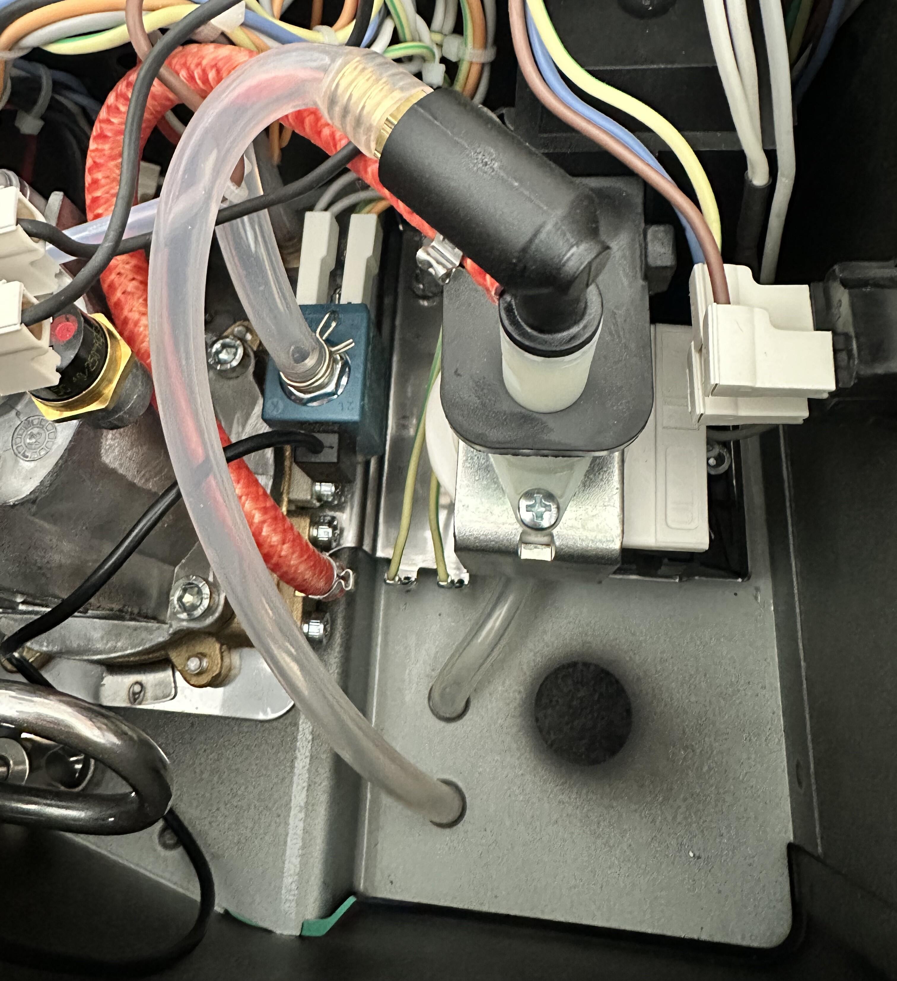
Both of the screws are screwed into the black plastic pump mount, and then attach to the bottom of the case.
To remove the hex-head screw at the back of the machine/pump, it is usually easier to unplug the wires with white Gaggia connectors from the rear power-connector. This makes accessing the screw with a hex tool / screw driver somewhat easier.
Once you have unscrewed the two pump mounting screws, you should then fully remove (just pull) the two silicone water pipes from the holes in the case (seen in the lower middle of this image) so that you will then be able to (carefully) lift and rotate the pump (along with the various pipes/wires etc.) and place the pump over the rear of the machine (as can be seen below) - which will leave the solenoid valve much more accessible.
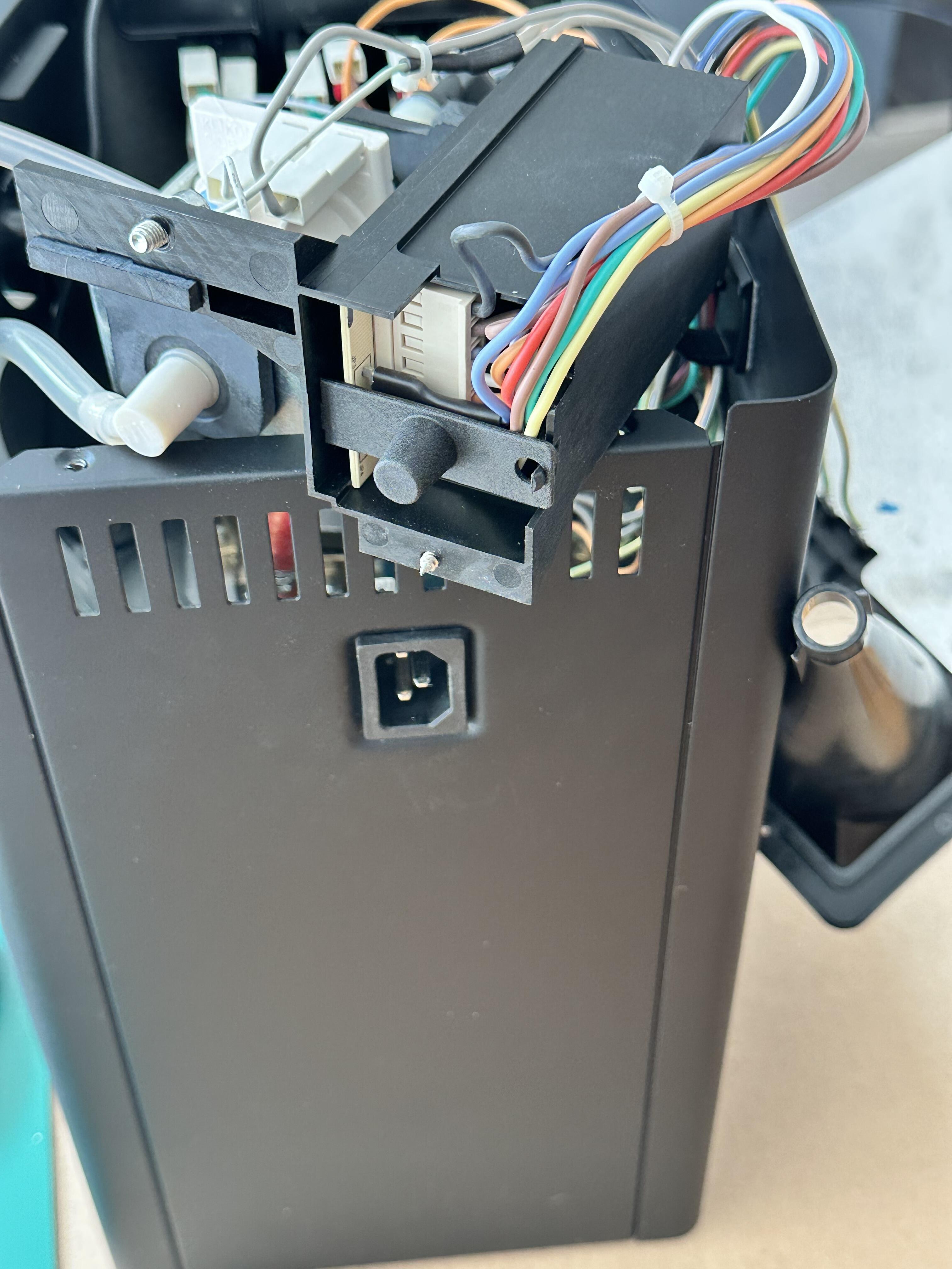
If you have an earlier Classic and can access the solenoid valve without removing the pump then you can resume from here...
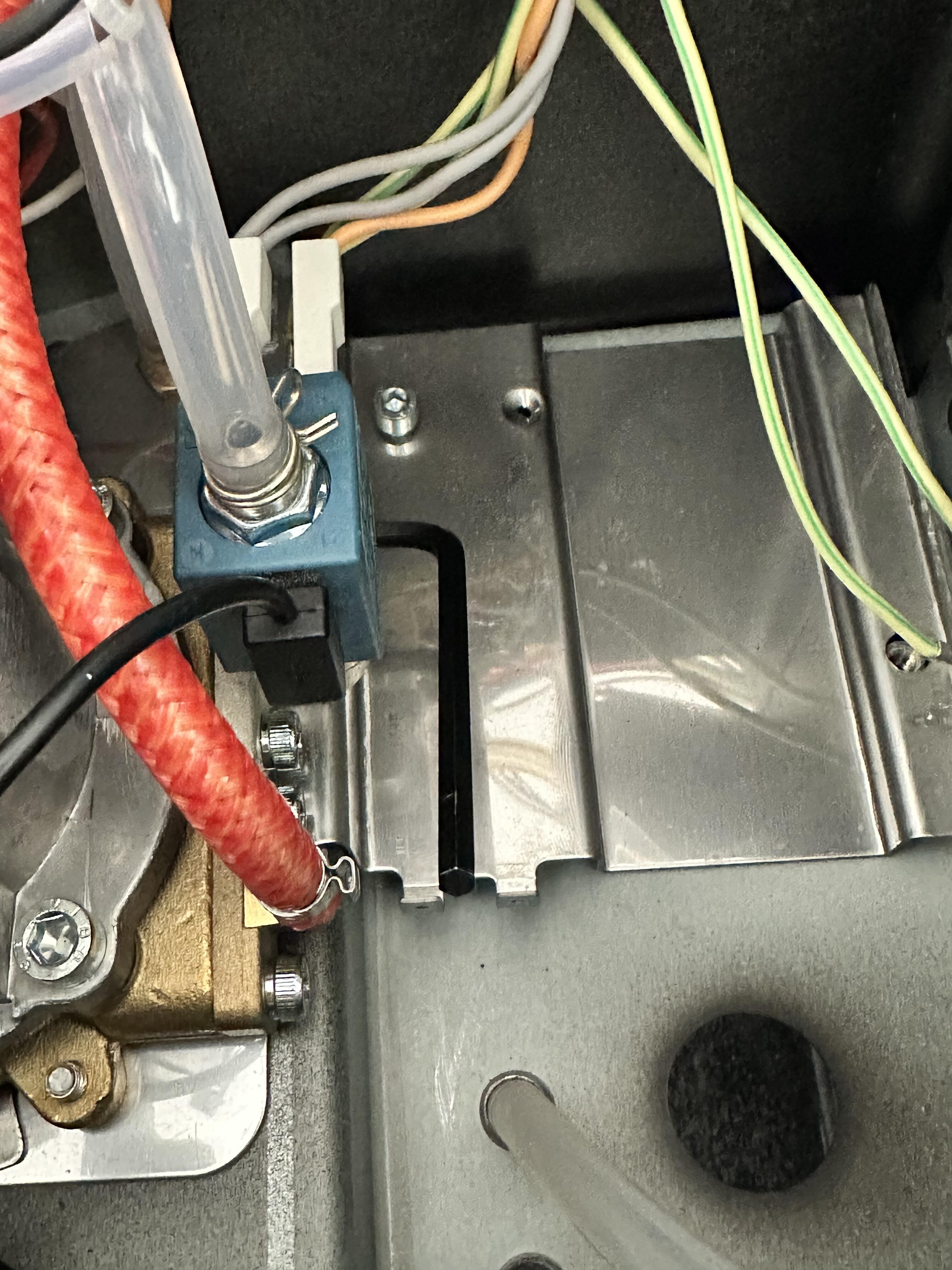
The image here shows the case with the pump removed, and the solenoid valve accessible. You can clearly see the location of the two pump mounting screws in this image - as there are holes within the metal plate where the screws attached.
Using a suitable (4mm) Allen Key or hex wrench you should remove the two solenoid valve mounting screws, that are attaching it to the group head.
We've placed an Allen Key tool on one of the solenoid valve mounting screws so that you can see the approximate location of it.
You can see the other solenoid screw within this image (just above the braided water pipe) - both of the solenoid valve screws are identical.
To remove the screws you simply insert your Allen Key / hex tool and then rotate (in the image here, you would press the end of the tool downwards) to unscrew.
As with many of the boiler screws (that are cycled hot/cold) it is VERY common for the initial rotation of these screws to be VERY firm initially - with significant force required. However, once the screws have initially 'cracked' then removal of them is usually quite simple and easy. Be sure to have your hex tool properly sized (4mm) and properly/fully located within the screw to avoid 'rounding off' the screw head and hence making removal and progress very difficult indeed!
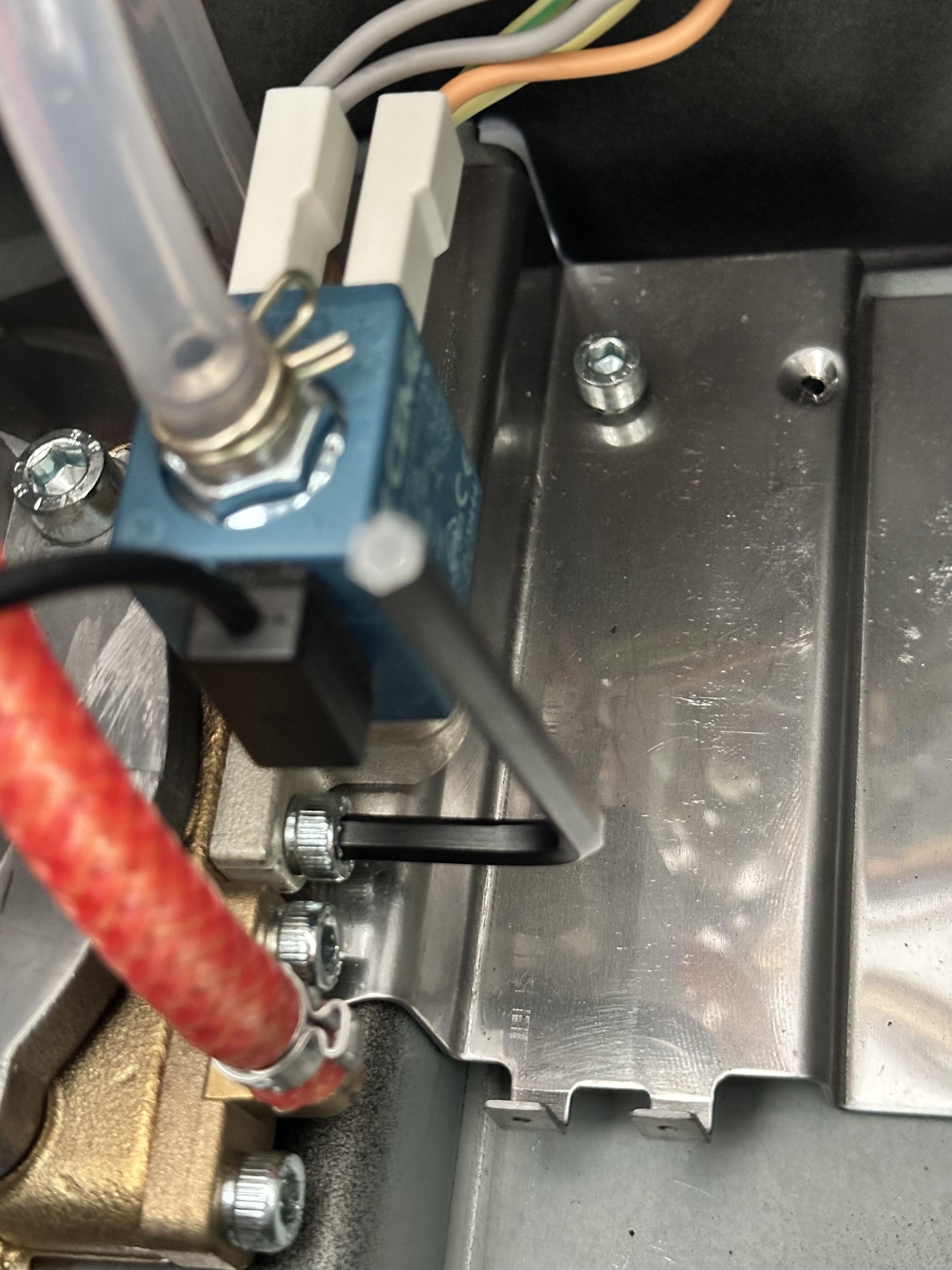
This image shows the location of the second solenoid mounting screw.
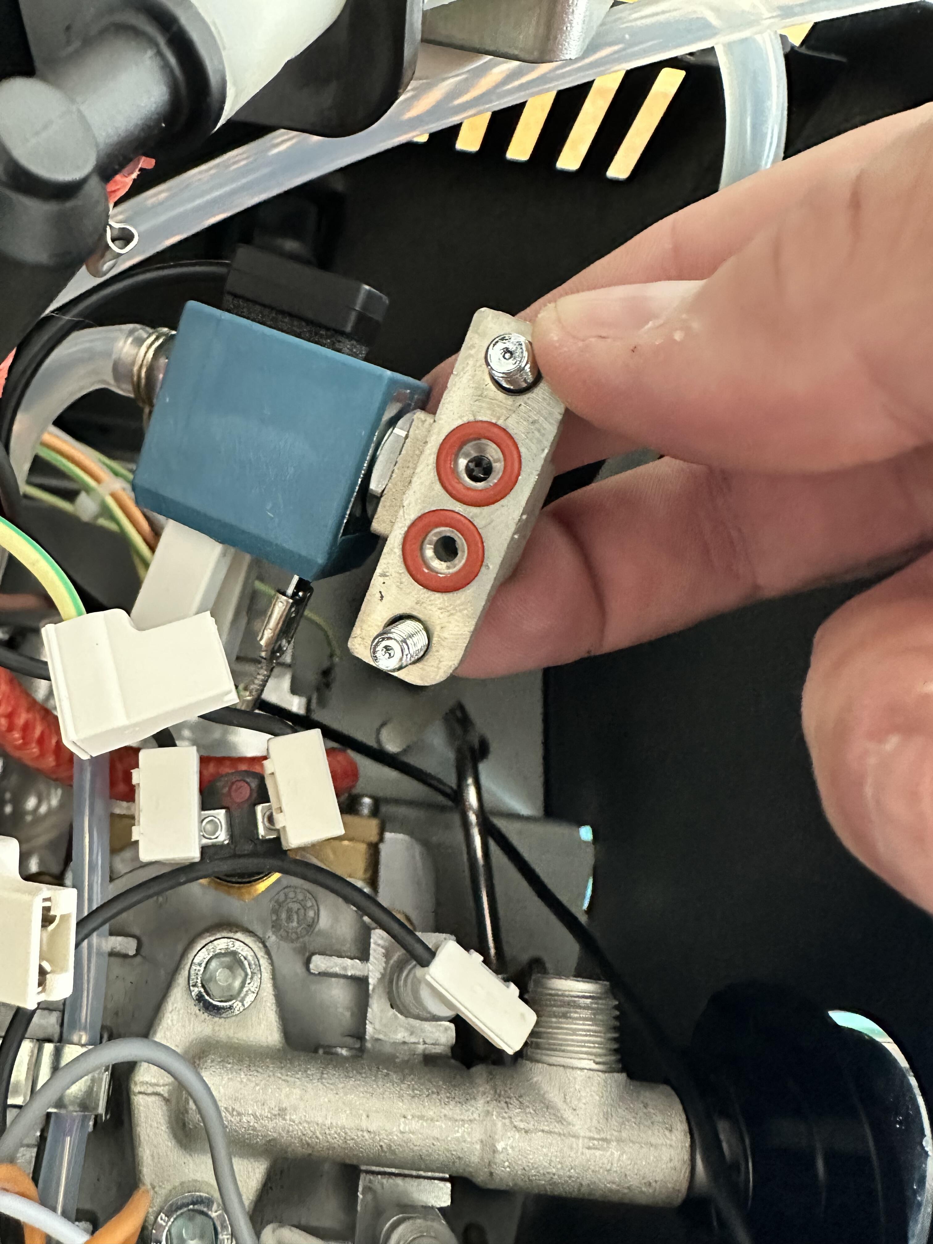
Once the two solenoid mounting screws have been loosened / removed you can easily just rotate the valve upwards as shown here.
There are two red silicone o-rings that are located within the indentations of the valve body - you can see them in this image. These will often come away with the valve (as shown) though it's also possible that they will (instead) remain on the group head.
Either way, locate the two red silicone o-rings / remove them from the group or the solenoid valve so that you have them both loose and the solenoid valve ports are both empty and have no o-rings within them.
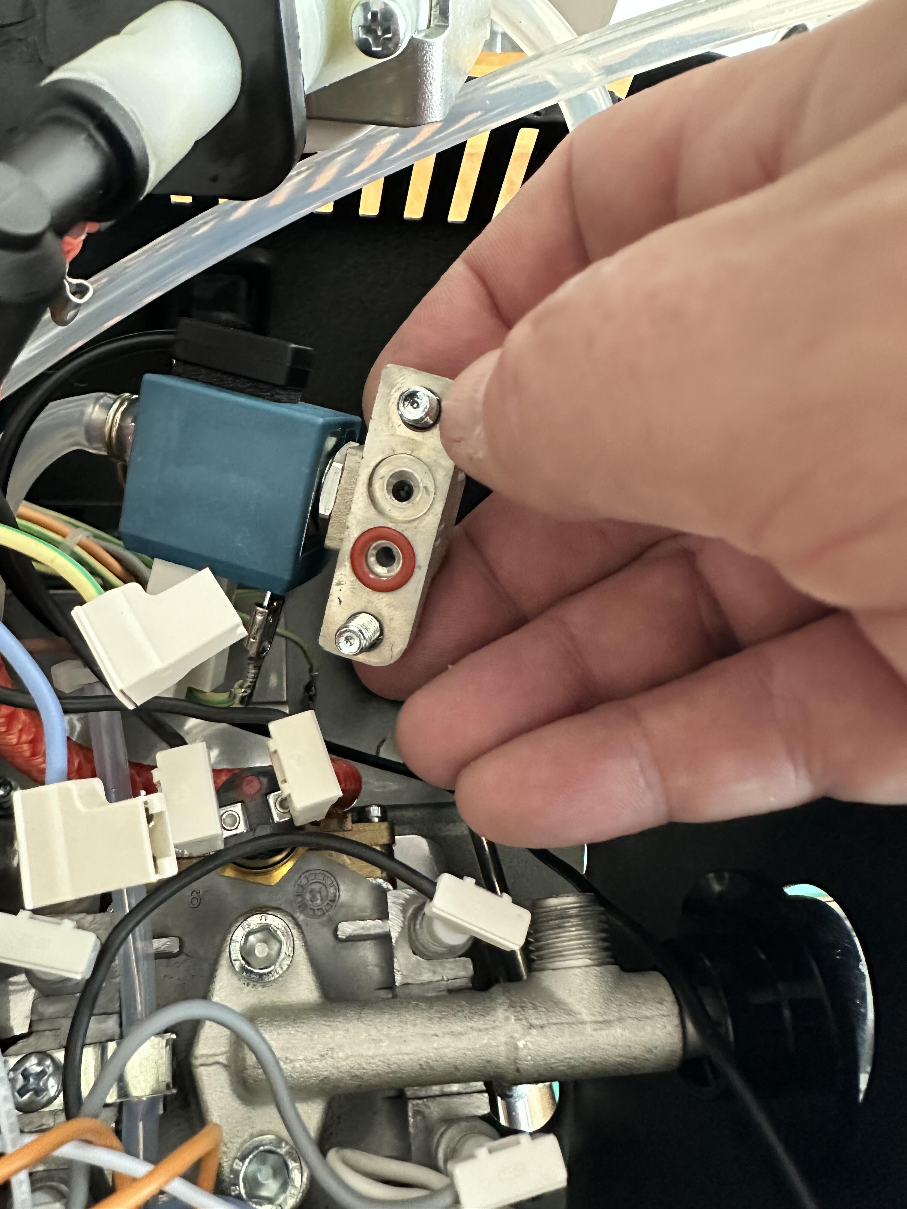
You should then firstly, inspect both of the o-rings and ensure that they are not broken or otherwise damaged. If they are, then you can replace one or both with the spare ones that we provide in the kit - though usually they are good for repeated reuse.
Once you are happy that the o-rings are good, or have replaced them, then place one of them in the LEFT port of the solenoid valve as shown here.
This port DOES NOT have or need a Solenoid Saver filter, as it's the output (not the input) from the valve.
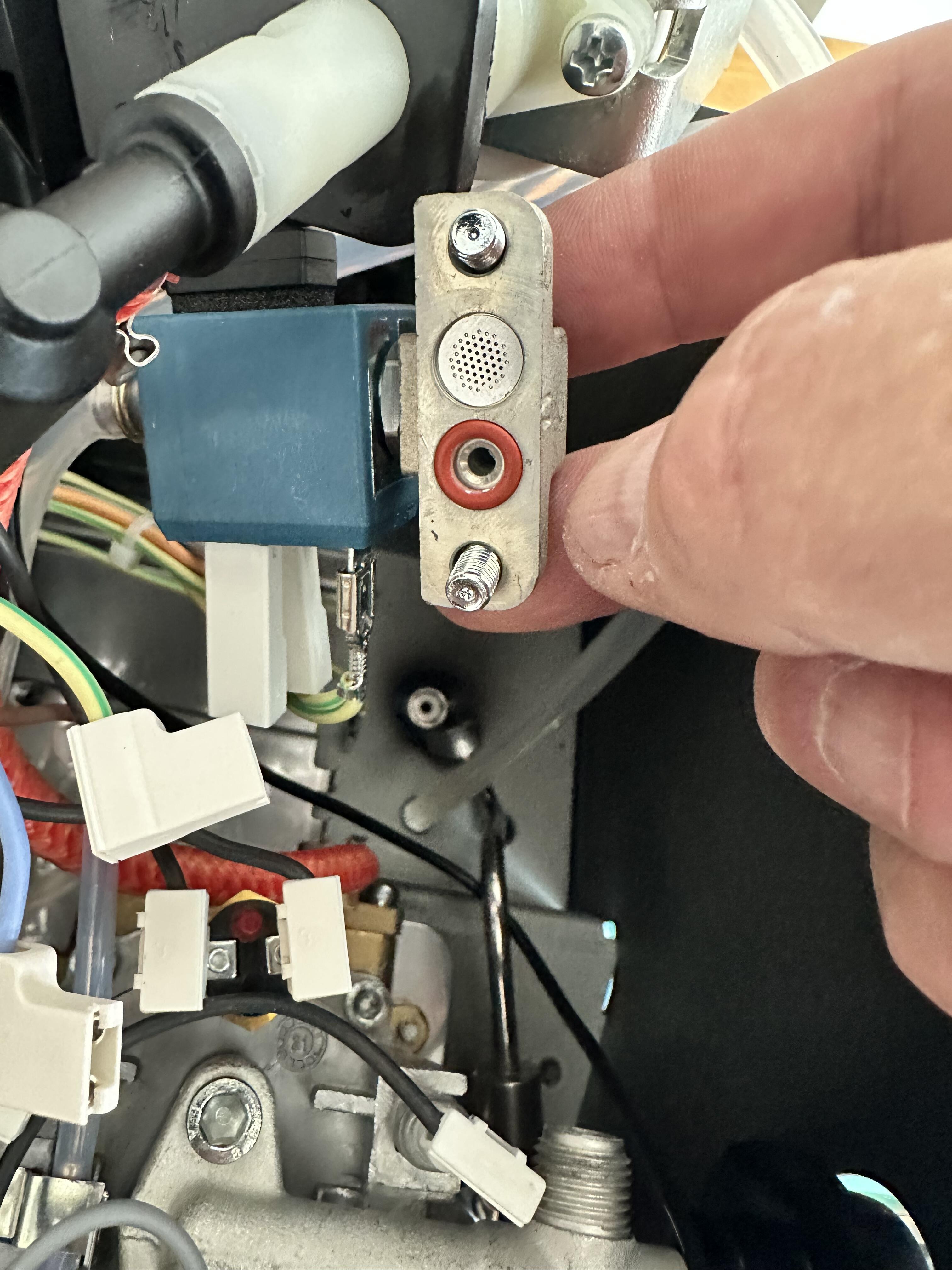
Next, place a Solenoid Saver filter within the RIGHT port of the solenoid valve (this is the water intake port, from the boiler).
The Solenoid Saver filter should be a good fit within the solenoid aperture and should sit flat within it.
Once you have placed the filter within the port, then also replace the red silicone o-ring within this same port, as shown in the image below.
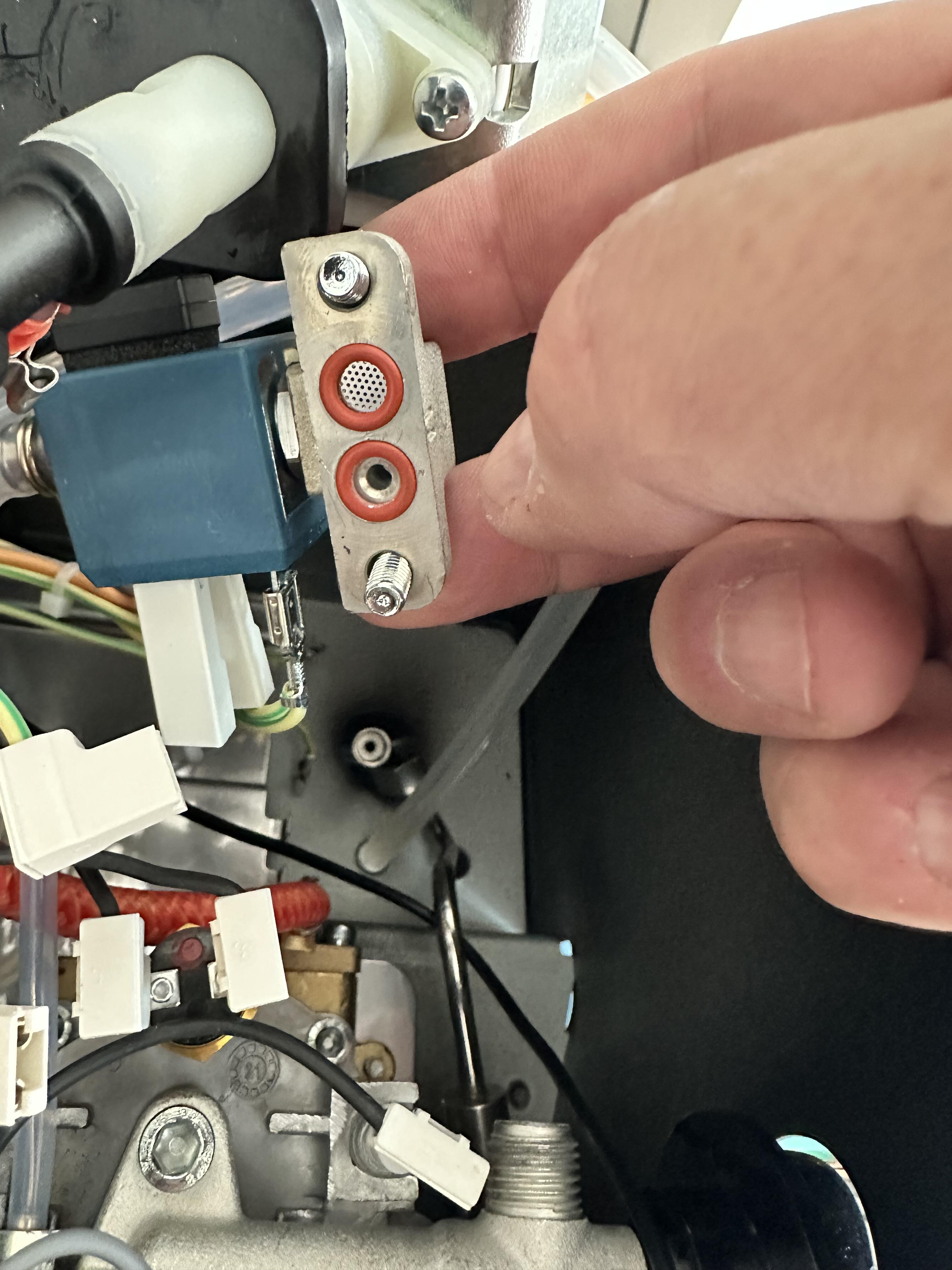
Once you have the solenoid valve looking just like this image, then you can carefully refit it in the position that it was initially in - carefully and firmly screwing in both of the retaining screws.
You should tighten these screws as firmly as reasonably possible - as high pressure water goes through both ports and if the screws are loose then water may leak from between the valve and group head.
If you removed the pump - you should then move/rotate it back into place - ensuring that the black plastic "foot" on the bottom of the plastic box next to the pump is properly located before doing so (you can see the proper position of it within an earlier image). Carefully fit the screws into the black plastic pump mount (you'll usually find it easier to place the screws into the pump mount before lowering it into place, or alternatively use a magnetic screwdriver). Then make sure that you place the two clear silicone water pipes back into the holes that you have removed them from previously (it doesn't matter which pipe goes in which hole). If you removed the rear power connector wires (brown/blue/green&yellow or black/white/green&yellow in some machines) then reconnect these in the same position as they were originally.
Testing for Leaks
Before you reattach the lid to the machine, it's usually a good idea to check for any leaks around the solenoid valve (or pump) now - and to do this the best method is to power the machine on, and use a blind basket to perform a water back-flush for a few seconds. Leave the pump running for 5-10s whilst you carefully look inside the case, around the solenoid valve and pump, for any signs of a water leak.
If your solenoid valve is leaking then it may be that your o-rings aren't properly positioned (or moved / fell out during fitting) or the mounting screws aren't tight enough - so try tightening the screws first, and if this doesn't work then remove the valve and double-check or replace the o-rings.
Finished!
Once you are happy that there are no water leaks, reattach the Classic lid - being sure to reconnect the green/yellow earth cable(s) if you removed them - and tighten the rear securing screws.
That's it!